July 5th, 2017
 A while ago, we started a discussion on the conductor. It seems like a relevant topic to re-consider in a multi-part series.
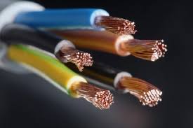
In analyzing the power distribution system in a building, the electrical engineer and designer can think of the panelboard as the heart, the conductor as the veins and arteries, and the electrical power as the blood. Continuing this analogy, the important characteristics of the conductor include whether it is fat or skinny, thickly or thinly dressed in insulation, and multicolored or monochromatic for phase and ground/neutral conductors respectively.
Most of the requirements of the National Electrical Code (NEC) are centered on the conductor. And there are many types: service conductors, service entrance conductors, feeder conductors, branch circuit conductors, ground conductors, and neutral conductor. Each type is part of the facility’s power distribution network allowing electricity to flow from the service at the power grid to the branch circuit load.
The factors to be considered in meeting the NEC’s meticulous and confusing requirements include: total load served, continuous and non-continuous load, coincidental and non-coincidental load, conductor insulation (TW, THW, THHN, etc.), system voltage and phase, voltage drop, temperature limitation, temperature correction factor, adjustment factor (number of conductors in a raceway), special conditions/applications (current carrying conductor and tap rule), ground electrode conductor, equipment grounding conductors, conductors in parallel, and load types (receptacle, lighting, or air conditioning). PowerCalc and the NEC
The complexity of this intertwined distribution network results in tedious calculations for the electrical engineer and designer. All are simplified with just 3 inputs per branch circuit by PowerCalc: load (kVA), load type, and number of poles.

The discussion of the complex requirements of the conductor will continue in our series on the conductor.
488 N. Federal Hwy, Boynton Beach, Florida 33435
(561) 278-9969
Inbound Performance Template by SmartBug Media. Copyright 2026.
All Rights Reserved
